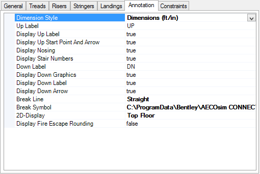
| Dimension Style
|
Sets the currently activated Style from the
Dimension Styles dialog. You can set the attributes of the arrow and text from
one of the predefined standard styles available in the Dimension Styles dialog.
|
| Up Label
|
Sets to display the
UP label in 2D geometry to be on
(True) or off (False). The
default is
UP.
|
| Display Up Label
|
Sets the
Up label display to be on
(True) or off (False).
|
| Display Up Straight Point and Arrow
|
Sets the
Up Straight point display to be on
(True) or off (False).
|
| Display Nosing
|
Sets the display of the
Nosing to be on
(True) or off (False) for stairs
with risers. Nosing is the overlapping distance of one tread to another.
|
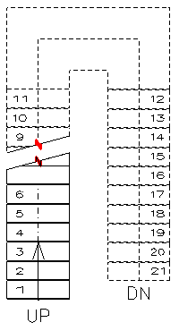
| Display Stair Numbers
|
Sets the display of stair tread numbers to be on
(True) or off (False). Stair
numbering displays in the 2D stair annotation. Stair numbering is a numerical
sequence label for each stair riser. The label is placed on the tread/landing
adjacent to the top of the riser. 2D stair annotations are visible in a 2D
model such as a dynamic view placed on a sheet or drawing.
|
| Down Label
|
Sets the
Down label display to be on
(True) or off (False). The
default label is
DN.
|
| Display Down Graphics
|
Sets the display of the
Down Graphics to be on
(True) or off (False).
|
| Display Down Label
|
Sets the
Down label display to be on
(True) or off (False).
|
| Display Down Arrow
|
Determines if a down arrow mark is displayed
(True) or not (False) in the 2D
representation preview and when the stair is represented in a drawing view.
|
| Break Line
|
Defines the break line to cut the stair 2D
representation at the breaking point.
The representation of the stair above cut section is shown
with dotted lines.
|
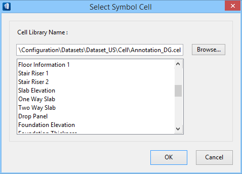
| Break Symbol
|
Sets one of the Symbol Cells from the Cell Library
located in the
Configuration folder. The path of the selected
cell is displayed.
The
Select ... option opens the
Select Symbol Cell
dialog and sets the break symbol from the selected
definition.
Browse... opens the
Select Cell Library dialog which allow
you to select a cell library to use as the break symbol.
|
| 2D-Display
|
Sets how the stair be represented in 2D drawing. The
one of the three options:Bottom Floor,
Middle Floor, or
Top Floor determines the 2D symbol.
- For Bottom floor,
displays the stairs assembly up to cut plane with outline of stair assembly
above.
- For Middle floor,
displays the stairs assembly outlined at cutline with multiple views of floor
below, and fixed distance from upper floor.
- For Bottom floor,
displays the treads that are above the cutline of the floor below.

2D Display property -
A: Top,
B
:Middle and
C :Bottom floor
The default option is
Undefined, when not set.
|
| Display Fire Escape Rounding
|
Sets whether to show (True)
or not (False) the fire escape rounding sign.
|